This week, I’ve just about completed finishing work on the Soyuz-SF Descent Module Interior (SDM) set. A major feature of this set is the complex console which has many lights and screens we want to be able to animate. These elements are represented by materials with “emit” values and video textures. Rigging textures and materials is a little tricky in Blender, and so here I’m explaining how I did it.
As with many things in Blender, there are actually many ways to do these tasks, with different advantages and disadvantages. For our workflow, it’s highly desirable that the things we want to animate are controlled by armature bones. So that’s how we’re going to set up our console controls. Note the ambiguity: we are controlling a fictional “console” from an armature “control panel” in the file. Although it would be just as sensible to reverse the terms, I will keep referring to them by the same terms to keep straight which I mean. One downside of this approach is that it uses some newer features in Blender — I believe you will need at least Blender 2.75 for this and have the “New Depsgraph” enabled, for this to work (it is certainly needed for the video rigging).
To start Blender with the “New Depsgraph”, you’ll need to provide a command line option: “–enable-new-depsgraph”. I’ve simply added this to the launcher in my XFCE (Ubuntu Studio) environment. You can also just launch the program from a terminal.

LED Indicators
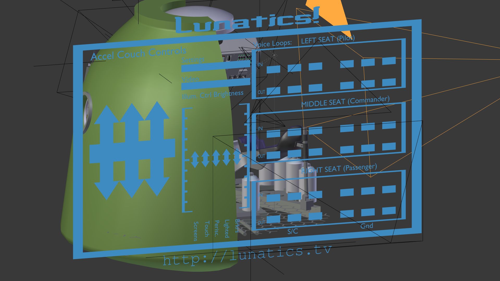
Note that that control panel has 45 LEDs on it! We need to be able to animate 36 of them independently (the breaker panel LEDs will at most flicker together, but each radio readout needs to be able to represent any state). There’s also some other illuminated buttons, and of course the two display screens and two touch panels, which have all animated graphics (there is also the periscope image below, which will be treated as just another screen, although at the time of writing this, I haven’t rigged that yet).
To make this as simple as possible, I’ll be trying to use the “DRY” design principle — “Don’t Repeat Yourself!” to avoid having to do highly repetitive tasks. What that means is that, whenever possible, I will want to define similar information all in one place. The most obvious example here is the material for the glowing LEDs. I clearly want them all to have a consistent look — but later on I might want to change the look (e.g. if I decided I wanted them to be red instead of green). That’s a material property, so ideally I’d have just one “lit LED” material defined, and all of the LEDs would refer to it.
But I also need to be able to turn LEDs on and off.
How can I do that with a single material for all LEDs?
Actually, I can’t. In Blender, if I want to animate the material for each LED separately, I have to have a separate material to animate for each of them. I spent quite awhile proving this to myself — I could not find any way to use, say, properties on the object or mesh to control the output value of the material.
But what I can do is to use a node-based material, concentrating the general LED glow properties into a node material, referenced by each object’s “slot material” (that is, the material which is in the material slot for the object). This means I have to create a separate slot material for each object, but can use a single material node for all LEDs.
I can do the same thing with video screens — providing the general properties of the screen glow in a material, while using a separate texture node to provide the image on the screen. Both are referenced in the node tree for the slot material, but the properties which all screens are to share can be represented by a single material node which they all reference.
Here’s what I came up with to do that:
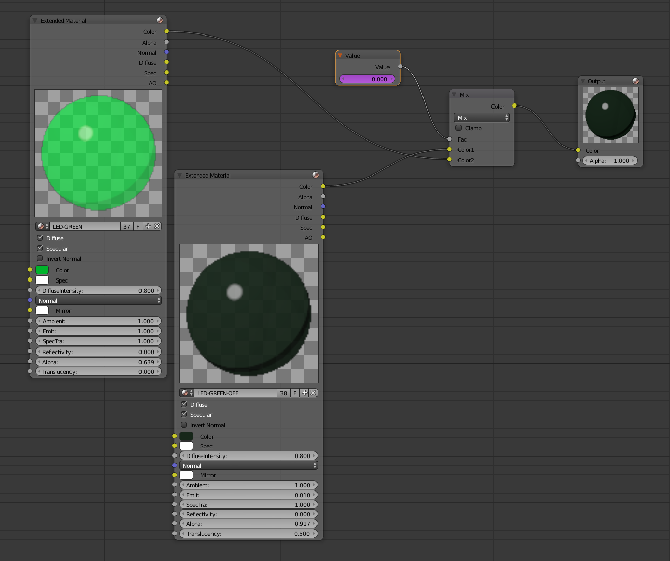
I have defined two materials, “LED-GREEN” representing the glowing LED, and “LED-GREEN-OFF”, representing the LED when it is not lit. Lighting the LED consists of altering the “Mix” node from 0.0 (all LED-GREEN-OFF) to 1.0 (all LED-GREEN). Note that it is possible to have a “half-lit” state if the value is somewhere between 0.0 and 1.0 — this is one advantage of this method over that of manipulating object visibility.
The “Value” node makes it possible to attach a driver to the mixing fraction control.
I can now control the brightness of this LED individually, using the “value” node, while leaving the glowing LED material effect as-is (note the number of users: 37 — one for each of the independently controlled radio LEDs, and one for the block of 9 breaker-on indicators, which I don’t intend to animate. Changing the properties inside the “Extended Material” nodes (both LED-GREEN and LED-GREEN-OFF) will change these properties for all of the LEDs.
So now all I have to do is to create drivers for each LED’s “value” node, and attach that to an armature bone.
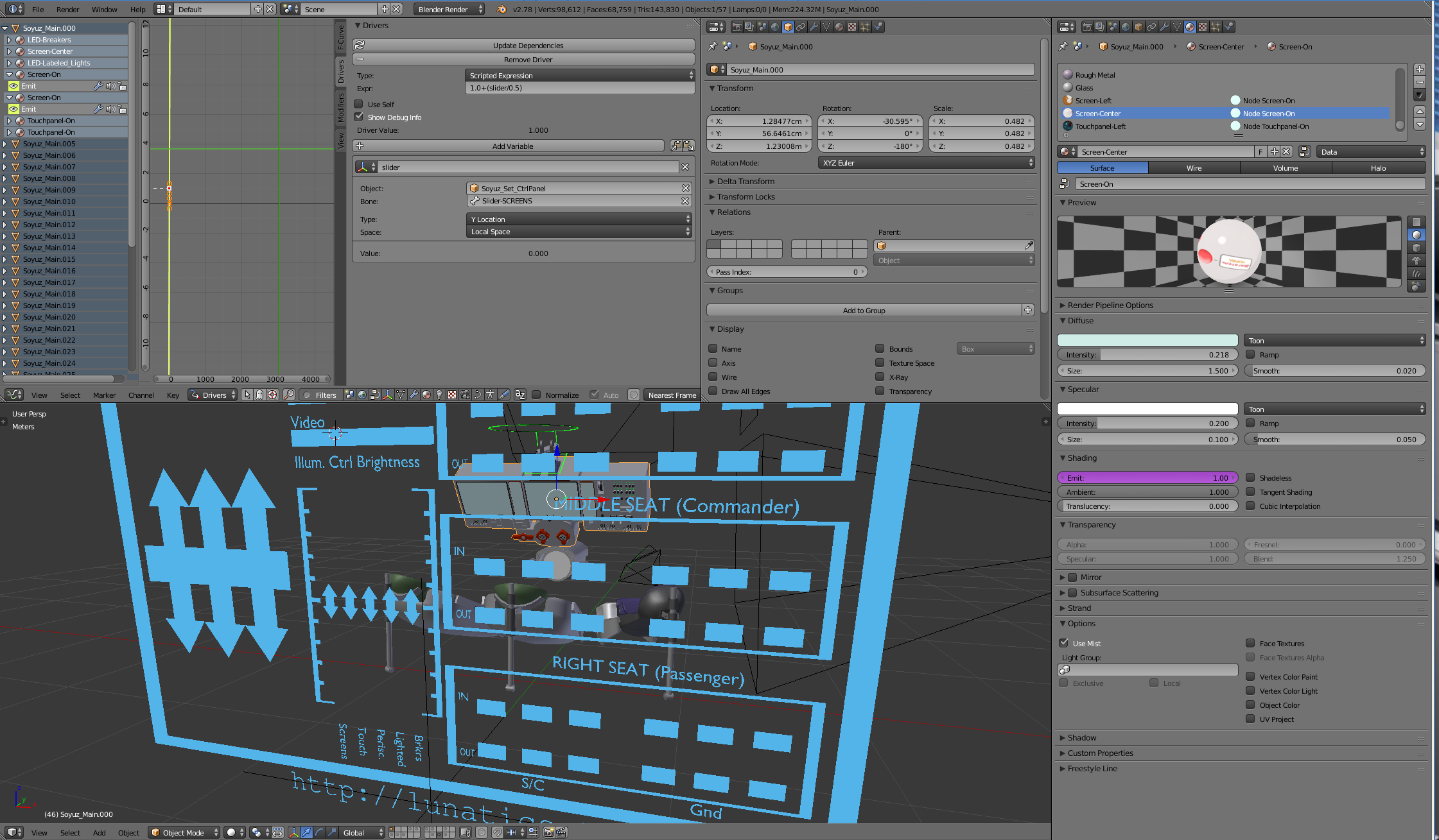
As you can see on my armature control panel, there are banks of sliders for the LEDs on the right side. Each is a free bone in the armature, with constraints that allow it only to move in the local “Y” direction and only by about 5cm. The driver maps this range from 0.00 to 0.05 to the range 0.0 to 1.0, used for controlling the LEDs. Here are the bone and bone-constraint panels for the control bone:

We also have to set up the driver that links the LED slot material’s “value” node to this bone for control. To do this, right click on the value in the node tree and select “Add Driver”. It is possible to use the “eyedropper” workflow to link to the bone’s position, but you may find it just as easy to use the manual process. In any case, here is the driver panel:
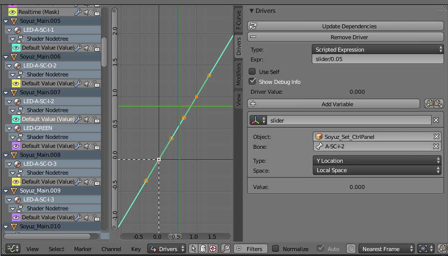
The expression “slider/0.05” simply maps the bone motion from the 5cm travel of the control to the 0-1 range desired to control the LED. We access the bone through the control panel armature (“Soyuz_Set_CtrlPanel” is its object name in the file) and the bone name “A-SC-I-2” which is a designation for this particular LED.
Note that when a driver has been added to property, its window in the UI changes to a purple color (as you can see in the node tree above).
The bone’s Y motion in its local space now controls the brightness of the LED.
Video Screens
The video screens are controlled in a very similar way. Here, though, I just want one control for the brightness of all the screens (by animating this, I can create a flickering effect that makes the screens look more “live”, and I can adjust their brightness to match the cabin lighting better).
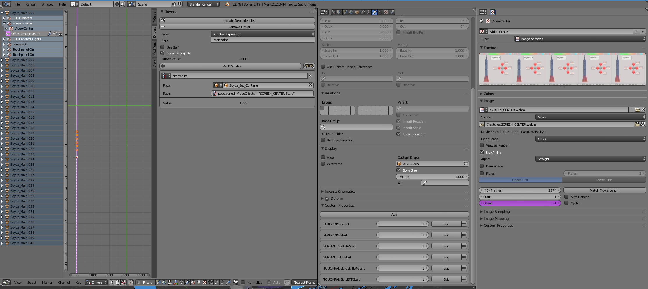
I also have another concern, though, with the video screens, which is how their animation effects are aligned with the action in the scene. We might not be using the same frame-number designations for the final scene in the production as we used for animated the displays. So we’ll need to adjust where the beginning of the animation starts. Ideally, we’d be able to control that with the armature, but I’m not sure I want to have an elaborate control graphic — this is something I can just type in and then let it be during most of the animation.
For that I create a new bone in the armature, which is completely constrained (it can’t be moved), but which has several custom properties. This is the “Video” text and the bar under it (both are combined into the “bone shape” for this bone):
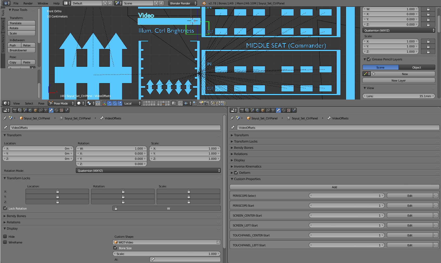
As you can see, all of the transform locks are turned on, so the bone can’t accidentally be bumped out of position, and I’ve provided controls for each of the video displays in the set (they’re currently all set to 1, meaning they’ll start at the beginning of the shot). There’s an extra control for selecting which video to use with the Periscope, which I won’t go into here.
The screen material node setup is also a little different:
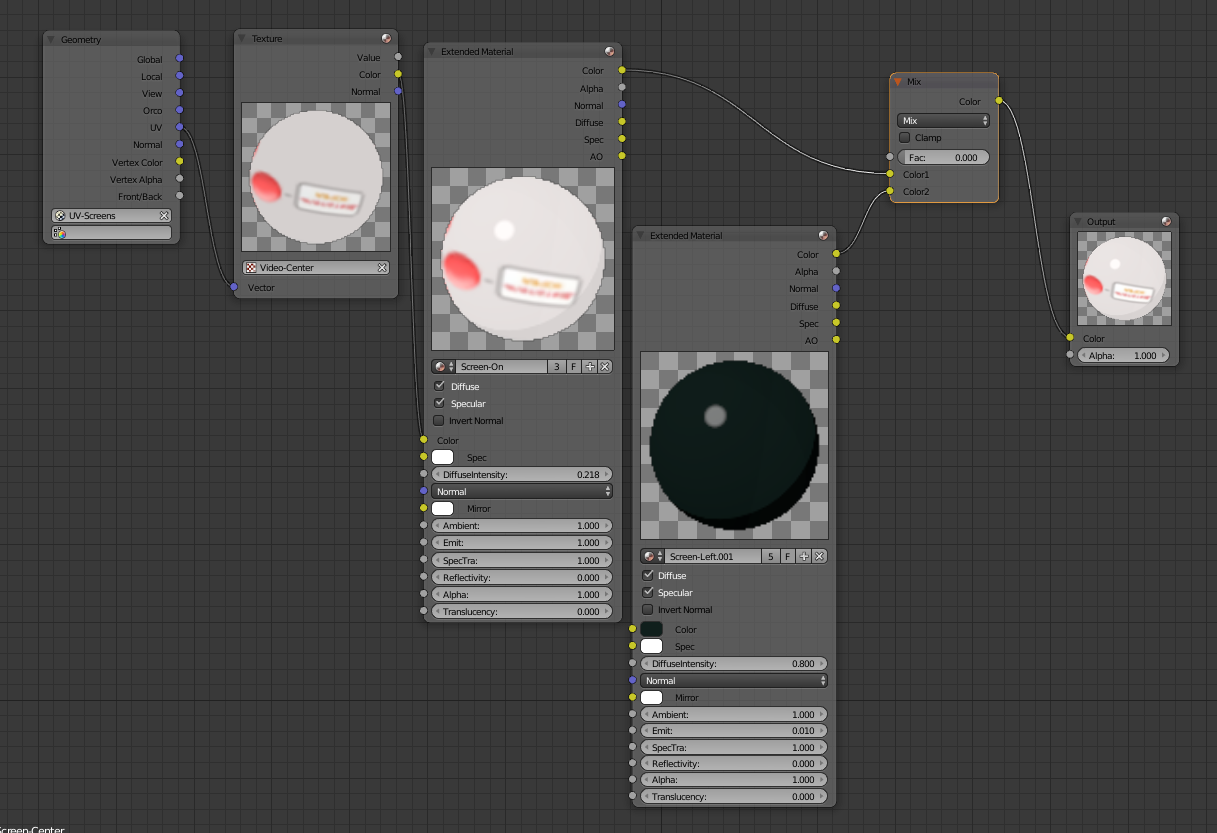
The mesh for the console includes a UV map with each screen mapped onto the whole UV space. There is a separate slot material for each screen, which is assigned to that part of the mesh. The texture determines what is displayed (this can be changed by altering the texture referenced in the texture node above). Although a blank screen material is provided, no control is provided for that (if I wanted one, though, I could add a driver to the Mix node, just as I did with the LEDs above).
You might notice there is no driver here!
That’s because the Texture properties do not appear here in the node tree. For that we need to select the Texture node and look at the Texture panel:
Now, I should warn you about a few “gotchas” about this:
- I already mentioned that this requires the New Depsgraph. If after you set all this up, the offset simply doesn’t update, the problem is most likely that you aren’t using it. Make sure Blender was started with the “–enable-new-depsgraph” flag on the command line. You might also need to be using Blender 2.78, which is what I used for this.
- The Texture property I am driving does not show up in the Drivers window unless the Texture is also used in a slot material texture slot — putting it in the node tree is evidently not good enough. The obvious way to do this is to turn nodes off and put the texture in the slot for the slot material, then turn nodes back on. This does appear to work, although I have not done extensive testing with it.
- You may need to make use of pinning for the properties panels to have one open for the armature bone and the material or texture at the same time — if you do, you can use the eyedropper tool to set the driver initially.
- Note that the “start” value for the texture cannot be driven — only the “offset”. This isn’t too limiting, as we can just invert the start point we want to get an equivalent offset (that is, the “scripted expression” in the driver is actually inverted from the number we set on the bone. Obviously you can refer to it as an “offset” instead of you prefer, but I find it easier to think of which scene frame I want the video to start on.
- The expression for identifying the custom properties of the control bone is pretty complex. You can get this by right clicking on the custom property and selecting “copy data path”. This will copy it to the clipboard, and then you can use “Ctrl+V” to paste it as the RNA data path for the driver variable.
- Note that the armature is referred to as an OBJECT, not as an ARMATURE in the driver panel. The armature UI doesn’t provide a way to refer to custom bone properties (which seems counter-intuitive to me, but that’s the way it works).
To control the overall screen brightness, I then set up a driver on the “Emit” property of the “Screen-On” materia (I actually made three different materials for this — one for the two display screens, one for the two touchpanels, and one for the periscope, so I can control them separately, but they all work the same way). This shows up in the Material panel, and is tied to one of the larger sliders shown in the armature control panel:
And that’s it for the Console controls. There are also some additional controls here that I’ll have to cover in a separate post.