This will be the first in a series of articles about converting a Primera Bravo II DVD duplicator into an M-DISC BDR / DVD / CD duplicator. My goal is to create a suitable duplication machine for commercial-quality print-on-demand BD-ROM and Lib-Ray video discs. As such, it is really part of my Film Freedom Project as I try to bring it back up to speed.
About the Primera Bravo II
This machine is a robotic disk duplicator, which incorporates an inkjet printer for direct-labeling of disks with a standard internal DVD burner, produced from the mid-2000s to about 2011. It allows you to load a set of blank DVD-Rs in one tray, and set up a job to copy a DVD image onto each disk, print the label on it, and then stack it in the other tray — a fully automated way to create a short-run of professional-looking DVDs, which is perfect for small studio or business use, where there simply isn’t demand for the runs of thousands of disks it takes for commercial DVD pressing, and you don’t want to hire an outside company to duplicate onto DVD-Rs.
Official support for these duplicators ended in 2021, making them now considered obsolete; so this is a kind of a retro-computing project, now.
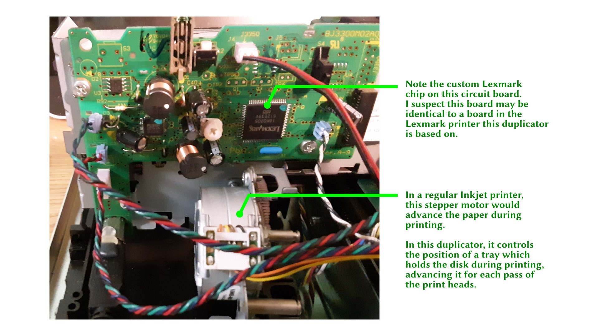
However, the Bravo II model is unique in that it was the only one with any official Linux support (but only for printing). The robotics were never fully supported on Linux by Primera, but have been reverse-engineered by hobbyists, although the information is a little hard to find. The printer unit inside is derived from the Lexmark Z600 inkjet printer series, and it uses the same ink cartridges. Probably, my biggest worry is that the print cartridges will become hard to find.
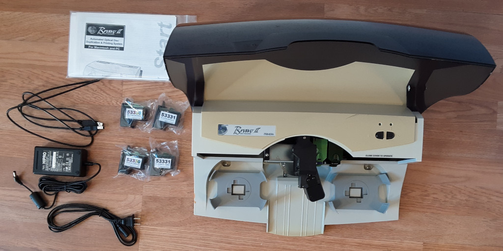
It is still possible to acquire used Bravo II duplicators from online sources. I acquired mine through E-Bay, last year. I got this particular one for $250, marked down somewhat due to the DVD drive not working (that is, the description reported it was not working). With the official support being dropped, it’s quite possible the prices will be lower now.
I was not concerned about the DVD drive not working, because my intent with this purchase was to convert the duplicator over to M-Disc BD-R media, which is my new preferred format for archival backups and for creating Lib-Ray discs. It will still be able to duplicate DVD and CD formats, of course, and the particular drive I have in mind will also burn M-Disc DVD-Rs. I will explore the media options, and the importance of this choice in a later article.
Breakdown
My first task is to do some reverse-engineering of my own. I have made some guesses about how this machine is engineered, but they’re only guesses, because I don’t have any design documentation. I also need to take the disk drive out of the machine in order to replace it with the upgraded drive. Again, I guessed this would be possible, but didn’t absolutely know this (spoilers: yeah, I think it’s going to work).
This is going to be fairly long and detailed, because this is also my documentation of the disassembly process (and my guide to reassembly!).
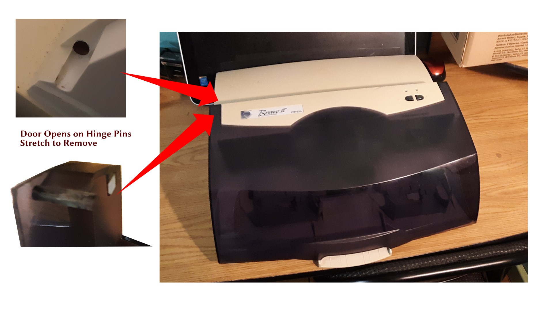
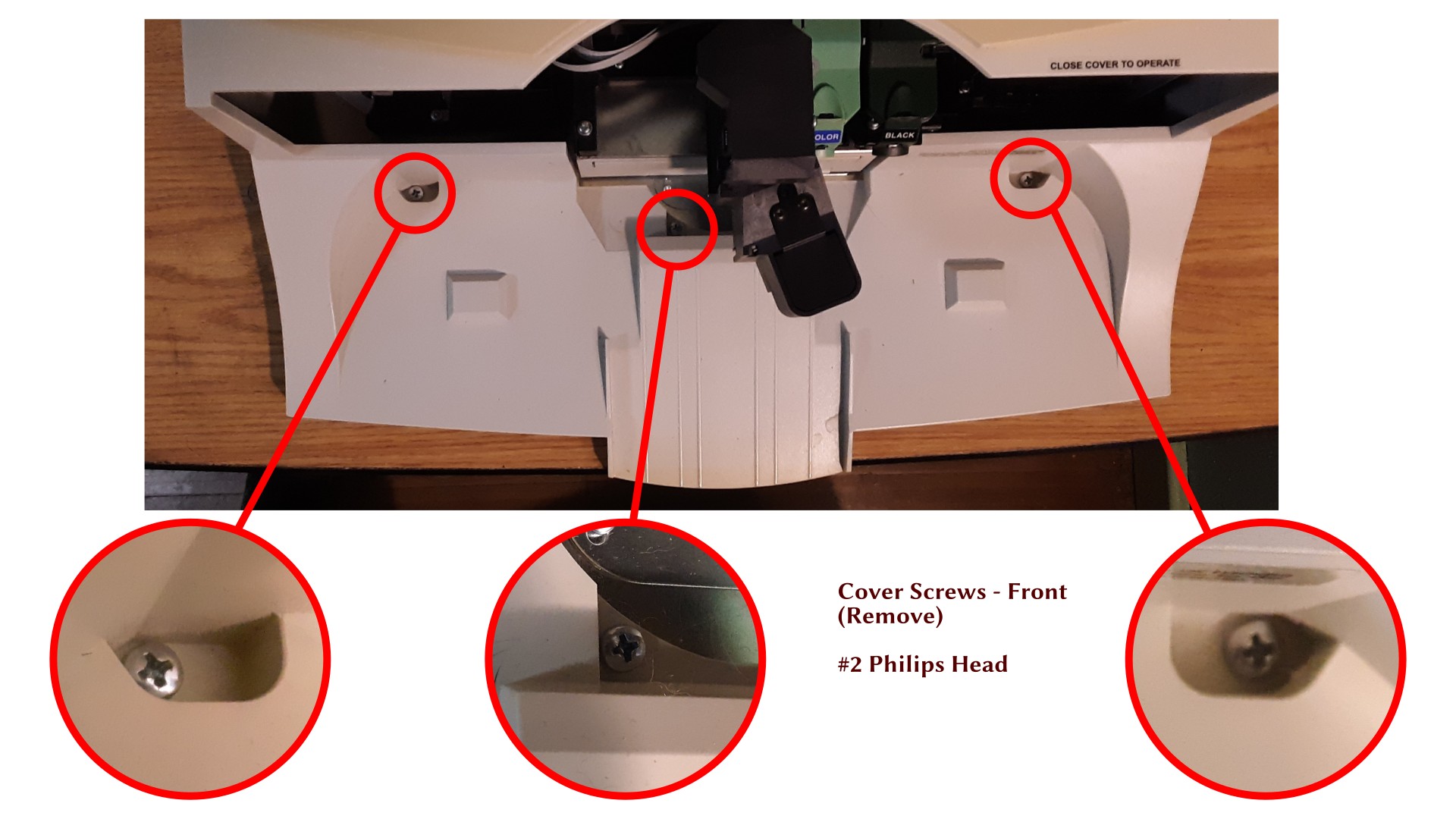
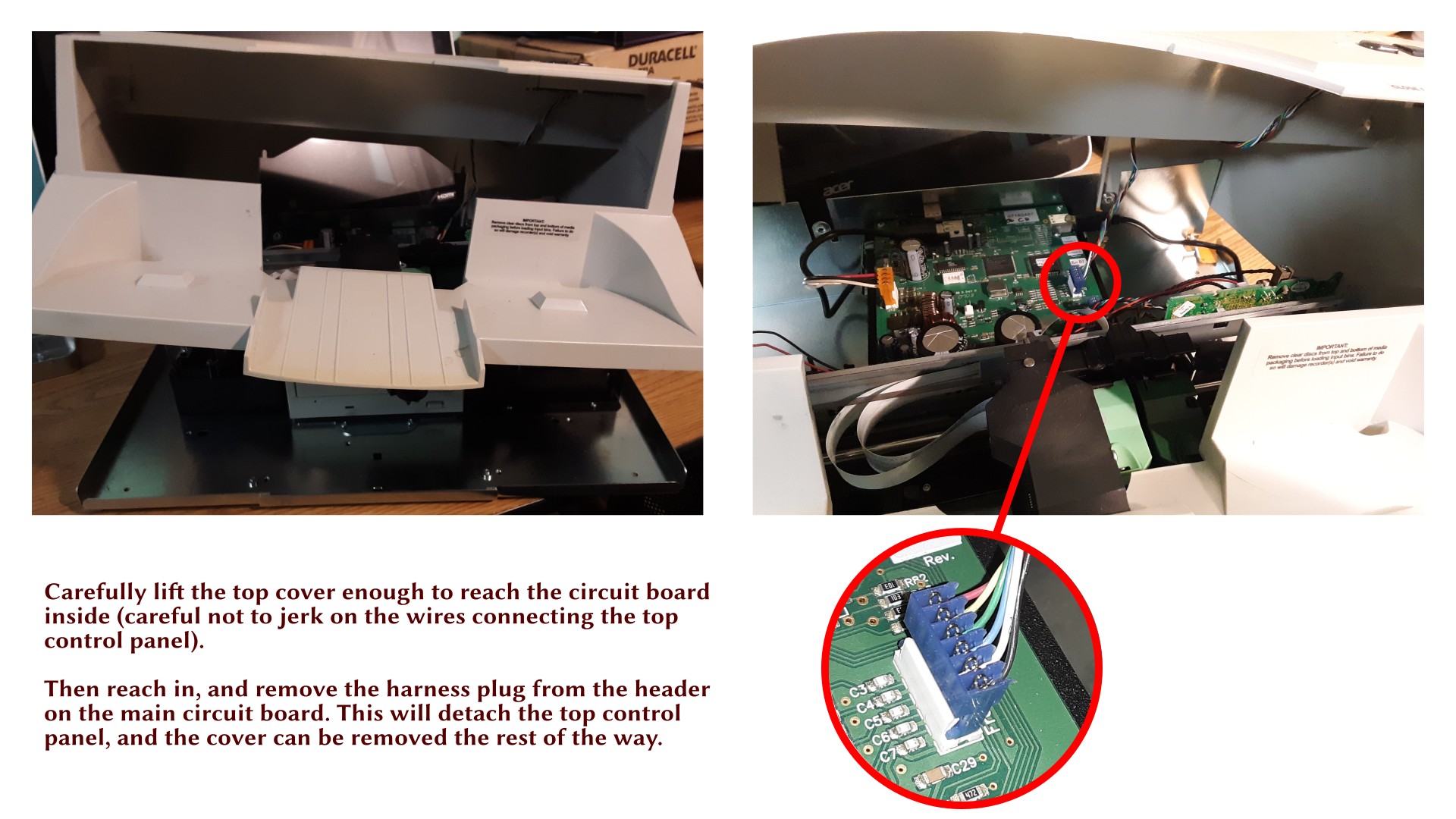
Removing the Cover

Examining the Interior Components
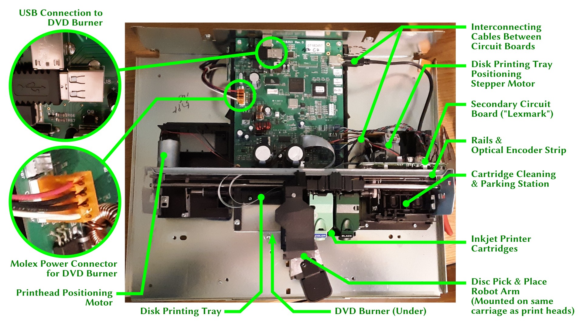
Now that we have the lid off, we can take a look at the components inside, and try to understand how this machine works. Fortunately, I once had a job doing tech support on inkjet printers, so I have a pretty good idea how the printer components work — these components are very familiar. The robot rides on the print carriage, which provides its left-right positioning. A stepper motor controls the position of the disk-printing tray, which sits above the DVD burner and below the main circuit board.
The robot arm has additional degrees of freedom to swing left and right, to lower and raise, and to grasp and release disks by their hub. This allows it to pick and place disks from: left disk holder, right disk holder, reject area (bottom center), DVD burner tray (when open), and disk printing tray (when extended).
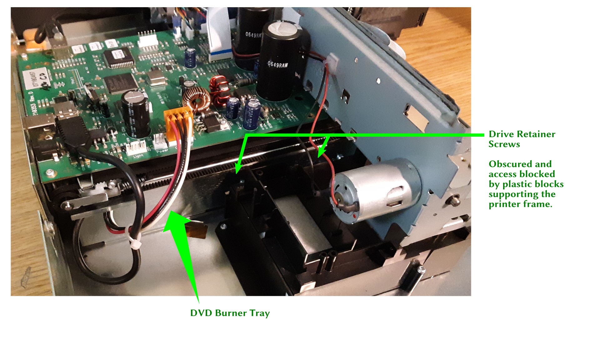
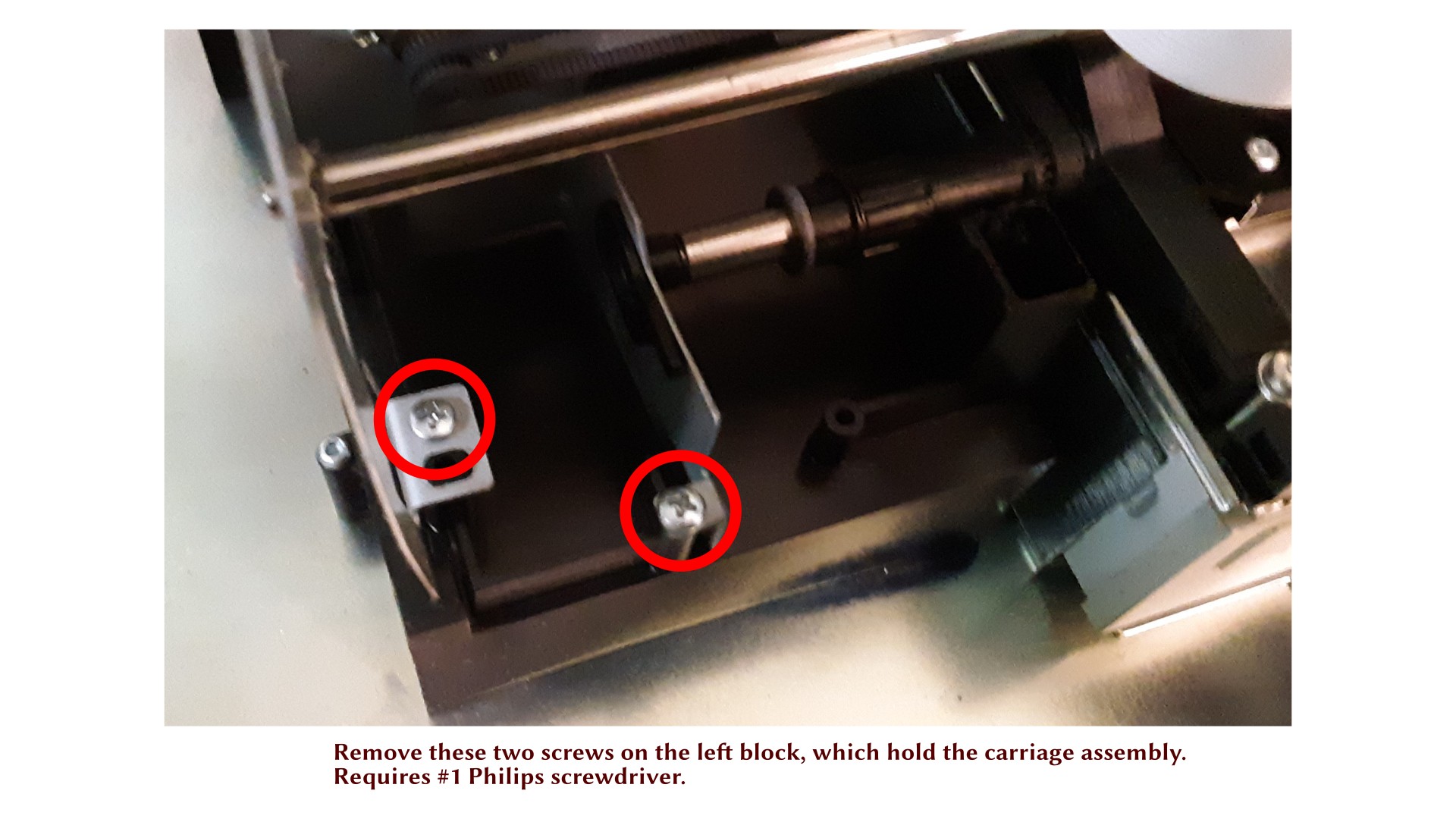
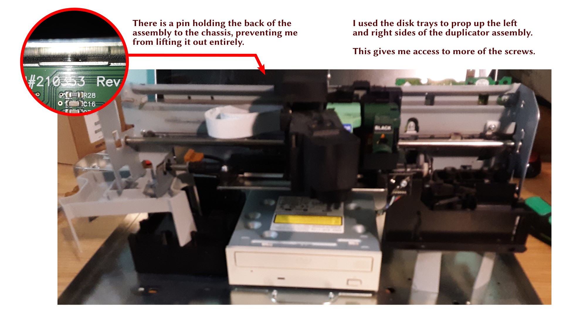
At this point, I’ve realized it’s quite a bit trickier than I had hoped to replace the DVD burner. It’s a standard mounting tray for an internal 5.25″ optical drive, all right, but the screws to release the drive are buried behind the frame for the printer and robot components. So I will have to carefully remove those to get to them.
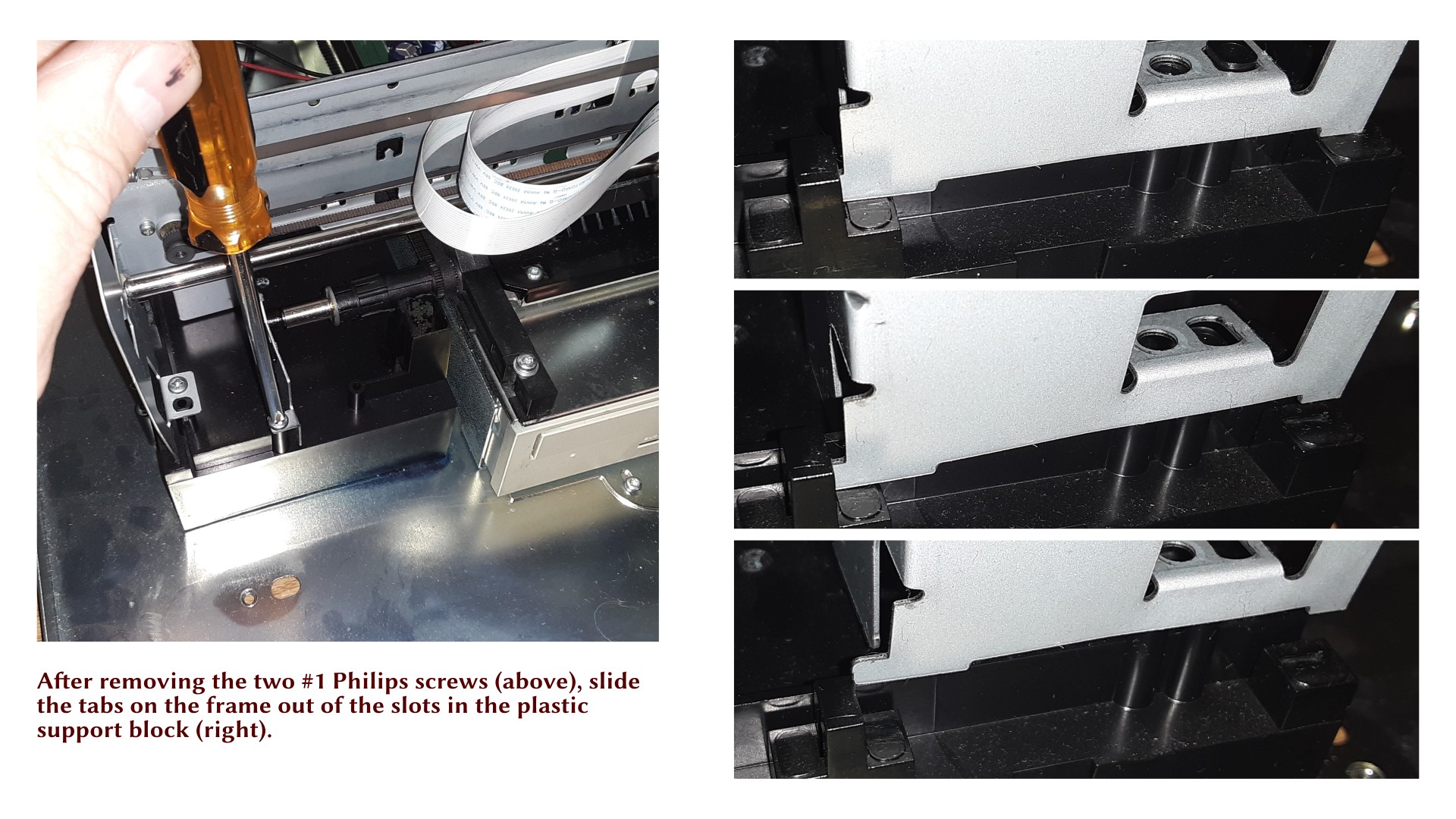
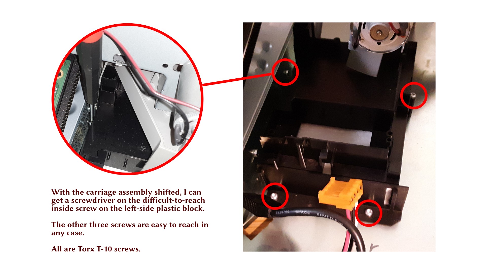
To make matters worse, one of the screws holding the left side block (the one shown in the illustration above) is directly under the rail, so I can’t get a screwdriver on that, either. As a result, I had to detach the rail assembly from the block first, then remove the block, and then I could get to the screws on the DVD. See the next section for illustrated steps.
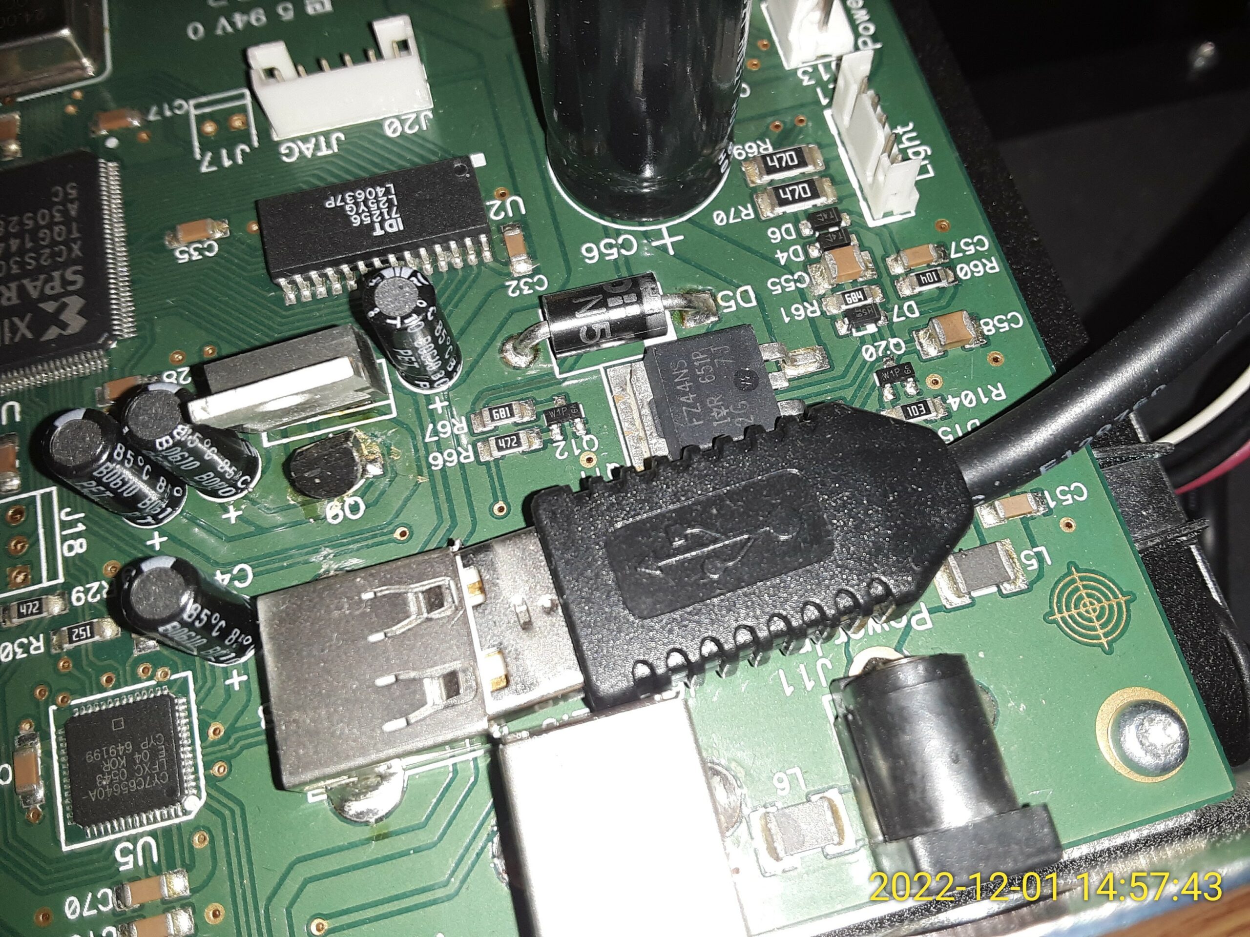
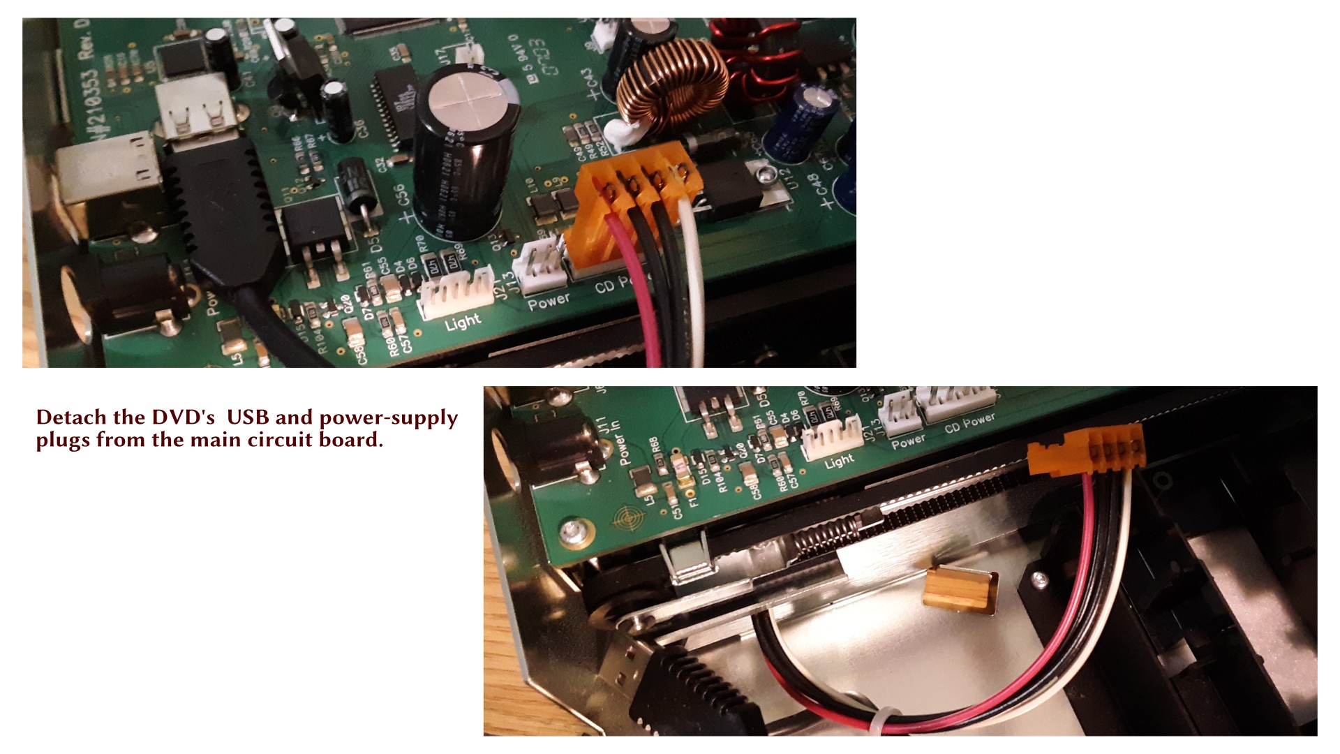
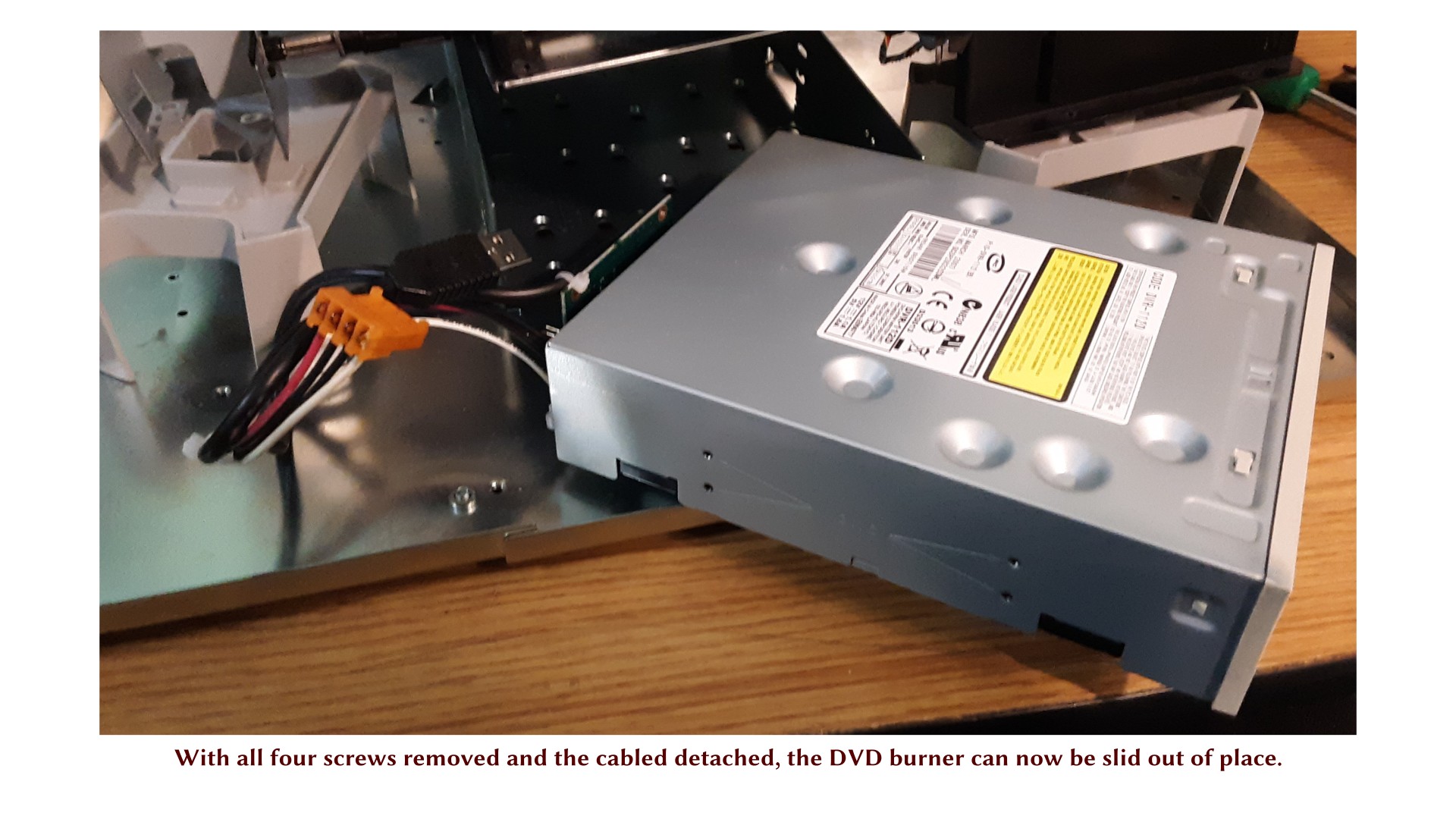
One curious aside: I think I know why the DVD burner was not working on this unit. When I first looked at it, the USB plug leading to the DVD was slightly pulled out of the socket. It was probably not making contact. What a trivial problem! I had assumed there was actually something wrong with the drive itself, but I think it was just this (and I later tested the drive and found it to be in working order).
Removing the DVD Burner
The next steps are required to remove the DVD burner, but I have to do several intermediate steps to get to it.

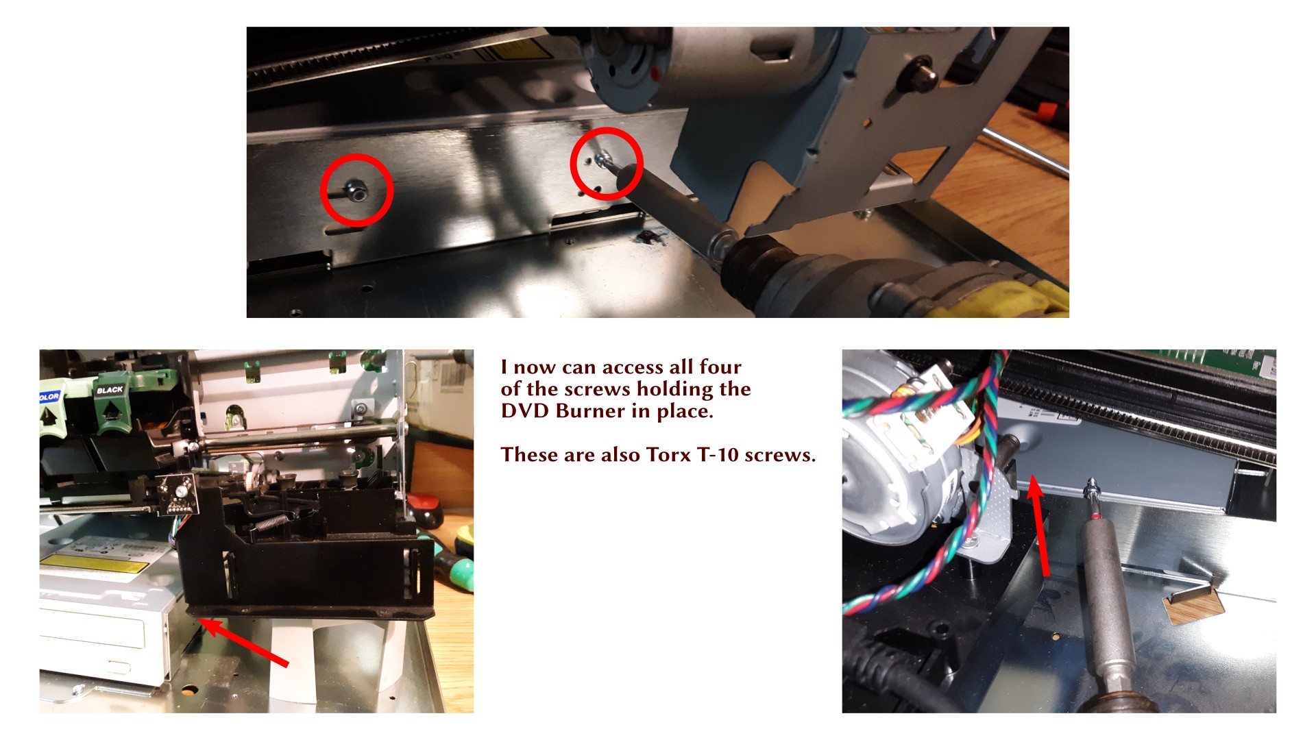
The rest of the screws in this process all have Torx T-10. Torx is usually a sign of two things: one, they want it to stay put, because Torx screws can be tightened more than Philips or flathead screws, and two, the manufacturer doesn’t really want you to mess with it, so you need to know what you are doing. Do NOT attempt to turn a Torx screw with a poorly-fitting screwdriver! A Torx T-8 will turn a T-10 screw if it is loose, but if any significant torque is applied, it may strip the screw head, and then you’re in trouble.
TO BE CONTINUED…
In the next installment, I’ll be examining the old DVD burner in isolation, and testing the USB topology of the machine as it appears to the controlling computer.